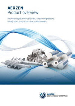
Positive Displacement Blowers
Positive Displacement Blower Stages
Series GM
AERZEN Positive Displacement Blowers are highly developed standard production machines designed and adapted to find use in a wide variety of applications. Robust 3-lobe blower stage for plant engineering. Suitable for a wide range of applications.
Volume flow:
17.658
to
38.259
CFM
Differential pressure (Δp):
-7.25
to
14.5
psi
Medium:
Air,
Neutral Gases
Conveying:
Oil-free
The advantages of AERZEN Blower Stages at a glance:
- Integrated pulsation reduction
- Housing consisting of: Cylinder (with two cylinder with cast-in pre-inlet channels at discharge side to minimise the sound by pulsation reduction), wheel housing, housing cover and side plates
US Units
Yes- Type of technology
- Positive Displacement Blowers
- Differential pressure (Δp)
- -7.25 to 14.5 psi
- Volume flow
- 17.658 to 38.259 CFM
- Medium
- Air, Neutral Gases
- Conveying
- Oil-free
For the oil-free conveying and compression of air and gases
Robust 3-lobe blower stage for plant engineering. Suitable for a wide range of applications. Available as standard in 22 sizes (GM 3 S to GM 1080 L).
Design
Blower with 3-lobe rotors and two cast-in preinlet channels in the discharge-sided cylinder part to minimize the sound by pulsation reduction. Housing ribbed and air-cooled. Blower cylinder undivided up to GM 400 L. From GM 430 S the cylinders are horizontally divided. Up to GM 80 L the feet at the blower are bolted on, larger sizes are cast on. Lube oil supply by splash lubrication.
Materials
Housing parts (cylinder, side plates, gear case and housing cover) made of GG-20. Shafts made of C 45 N and rotors made of C 45 N (GM 3 S up to GM 80 L) shafts and rotors are forged in one piece. On size GM 90 S and GM 130 L pistons and shafts are cast of one piece EN-GJS-500-7 (GGG50). Rotors made of EN-GJS-400-15 (GGG40). (GM 150 S up to GM 1080 L) helical timing gears made of 16 Mn Cr 5E. If you have questions about any other materials please contact us.
Shaft sealings
Conveying chamber seal by 4 piston ring labyrinth seals with oil slingers at each shaft end. On request, 4 radial seal ring-piston ring labyrinth seals are available. Driving shaft seal by radial seal ring. In case of gastight design of the driving shaft 2 radial seal rings are used with an intermediate grease trap.
Direction of flow
From top to bottom (vertical)
Position of the driving shaft
Left (viewed onto the driving shaft) alternatively the driving shaft is possible at the right
Drive
Overhung drive via narrow v-belt, directly driven via flexible coupling or with gearbox.


